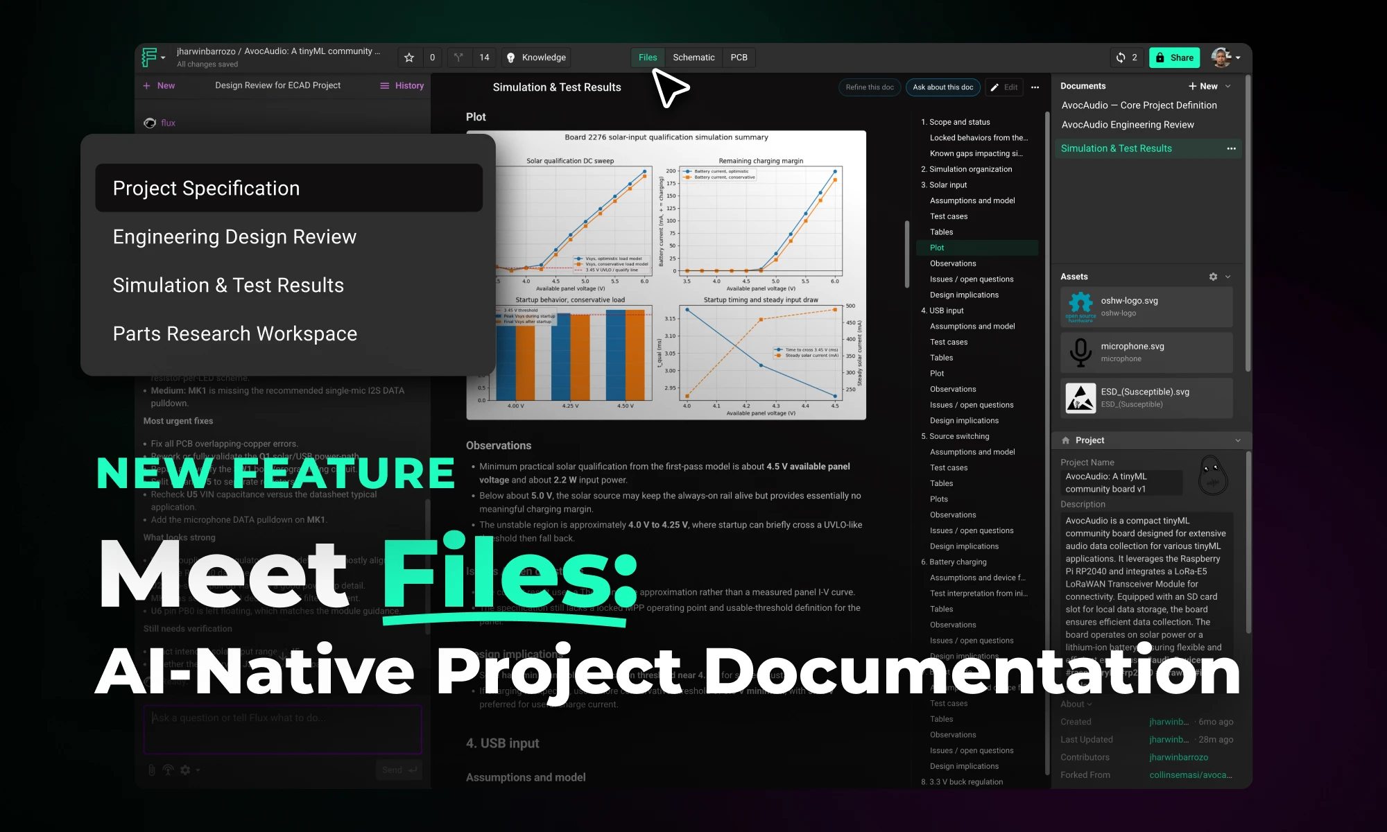
Files is a new top-level tab in Flux projects that centralizes all project documentation, including specs, uploaded assets, generated outputs, and project descriptions, in one place. This gives Flux full access to your project context, enabling better outputs, continuity across sessions, and easier team collaboration.
Discover how Copilot transforms hardware design from concept to creation through an end-to-end example of designing a webcam, showcasing the power of AI hardware design at every step.
This project will be designing the camera circuit for an open-source laptop. We’ll be starting completely from scratch to design a functional webcam around OmniVision’s OV02740 HD image sensor, and we’ll be covering everything from the image sensor itself to the supporting power management and passive circuitry. At the end of this project, you’ll see exactly how AI can reinvigorate your PCB design process from start to finish.
The major AI-powered steps in this project will include
You can check out the projects at your own pace using the links below
The first challenge when starting a new project is taking your idea for a product and deciding on the design architecture. The architectural design phase is foundational in hardware development, sometimes determining the success or failure of a project. It's complex, requiring the balancing of numerous variables and aligning diverse stakeholders on a unified vision.
Creating architectures with Flux Copilot is easy and straightforward. You can simply have a conversation with Copilot about what you intend to build using as much information as you know. Copilot can use your requirements and constraints to explore many different architectural ideas and variations quickly.
In this project, we started by asking:

Copilot then provides us with multiple architectural options, each containing suggestions for circuit blocks, components, and their interconnections. Later, Copilot helps us create block diagrams to better visualize and intuitively understand our chosen architecture. Leveraging AI to rapidly generate and evaluate a wider range of options against your specific product requirements ensures a more effective selection process that leads to optimal outcomes.
To learn more about AI-powered architecture design, read our blog.
Once our architecture is determined, we need to choose the core components that will turn our idea into a real circuit. Fortunately, selecting components is one place where Copilot really shines.
Copilot is guided by your company’s guidelines, including regulatory requirements, pricing, power consumption, operating conditions, and more. With these parameters defined in a Template, Copilot finds the best components that fit your specific project requirements.
In this project, given our architecture, we ask Copilot:

Copilot then provides specific components that are interoperable and achieve the needs of our design in an organized, tabular manner.
Learn more about how AI powers component research.
Designing electronics is about more than just creating a system that works; it also requires creating a system that is sourceable, compliant, and robust against a volatile supply chain. Once we have decided upon our main components, we can use the power of AI to help find alternative component options in case we need backups for whatever reason.
For space savings in our webcam project, we ask Copilot to help us find leadless package alternatives for our components. Specifically, we can ask Copilot

Copilot then provides us with an alternative component that meets our architectural needs and even describes the differences between the original and alternative components.
However, we run into a problem here: the new component doesn’t have a part in the Flux library yet. Fortunately, we can use Copilot to automatically generate a part (i.e., schematic symbol, footprint, and 3D model). Our AI-powered workflow allows you to create parts by importing PDF datasheets directly. Copilot will automatically extract part information, generate components, and enable easy review, validation, and editing—all within the browser.
This AI-powered workflow for handling datasheets and part creation offers an entirely new way to approach the task, replacing the tedious and time-consuming manual part creation process.
Want to learn more about AI-powered part creation? Read our blog.
Thanks to Copilot, we have a schematic and component alternatives for our webcam project. But next, we want to try to make this design as affordable as possible. It’s time to cost-optimize our design.
First, we can save costs by eliminating any unnecessary components in our bill of materials (BoM).
BoM consolidation involves identifying outlier components that can be merged with existing values, reducing the number of unique components needed. For example, a circuit may require a unique resistance value, such as 31.23kΩ, but such a unique value is costly to source. Instead, Copilot can suggest implementing this resistance with two more standard and affordable solutions, such as a 30kΩ and 200Ω in series.

Then, Copilot can help us save costs by evaluating components for over-specification. This ensures that no component exceeds the necessary performance requirements, which can reduce costs. Learn more about AI-driven PCB Cost optimization.
For example, assessing whether a high-performance microcontroller is necessary or if a lower-cost alternative can meet the project’s needs without compromising performance. Copilot can investigate the components in your schematic against the operating conditions of your circuit — be it power, temperature, or frequency — to ensure that no component is unnecessarily over-specified.

Now that we have a highly optimized design, it is time for a design review. Follow this blog to learn more about AI-powered design reviews.
Reviews can be meticulous and tedious, demanding the near-impossible task of considering hundreds of variables and comparing your design against organization-specific standards and constraints. AI like Flux Copilot can automate these menial tasks so that engineers can save time and instead focus their efforts on more high-leverage tasks.
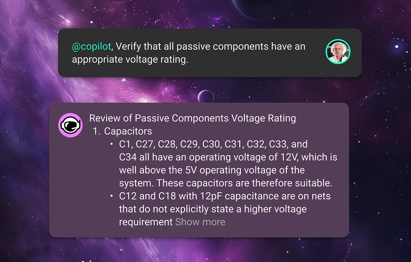
In this project, we ask Copilot first to review the voltage ratings of our passive components. Copilot can handle this task without further instruction, but in this case, we give Copilot detailed steps on how to complete the review so that we’re confident that the review is up to our standards. Copilot then compares every passive component’s ratings against the maximum applied voltage in our circuit and provides this data, as well as a pass/fail status, in an organized table for our review.

Then, we take things one step further by asking Copilot to conduct a precise design review focused on verifying the pin-out and configuration accuracy of the components in our schematic. Copilot gives us insight into its design review process by first explaining the procedure it will follow during its review. With our permission, Copilot then validates the pin-out of our components against the datasheet and provides the results in an organized table.

The final step in our design process is now the testing and debugging phase. Flux uses AI to help you test and debug your circuit designs, including everything from test plan creation to failure mode and effects analysis (FMEA).
In our webcam project, we first asked Copilot to help us develop an automated FMEA report that identifies critical failure modes, assesses their impact, and recommends mitigation actions based on severity, occurrence probability, and detectability. Copilot took to the challenge, generating a detailed tabular report of each component type and explaining the table. With an understanding of the detailed interplay between all the components in your design and expert-level knowledge of electronics fundamentals, Copilot creates a thorough and comprehensive FMEA report for us.
Next, we asked Copilot to help us create a detailed step-by-step plan table for this project to verify its functionality. In our case, Copilot responded with a test plan outlining steps for each major component and functional group. To learn more about AI-powered testing and debugging, read our blog.
With a comprehensive test plan, your team can ensure that any design errors get caught early in the process and well before you go to production. This means your team can spend less time correcting errors and less money on unnecessary design revisions. Ultimately, that translates to higher quality products and faster time to market.
AI has the power to completely transform the hardware and electronics design workflow from start to finish. Through this end-to-end project example, we hope to have demonstrated how AI can assist your team’s design process and how each unique AI-powered workflow converges to create an innovative product. To learn more about how your company can streamline processes, reduce costs, and save time with AI-powered hardware design, sign up for Flux today.
Flux Copilot helps your team tackle the complexities of PCB cost optimization, identifying hidden savings and providing engineers with actionable insights to streamline design processes and reduce costs.
The process of cost optimization in PCB design is notoriously multifaceted and time-consuming. Typically, it involves reviewing hundreds of components for cost and necessity and considering multiple optimization options for each. Each alternative option then needs to be evaluated against a sea of competitive products for technical viability and sourceability.
Needless to say, this process is time-consuming, and the chances of missing potential optimizations are extremely high. Realizing design optimizations without sacrificing functionality and reliability can be overwhelming.
Fortunately, we’ve developed Flux Copilot to be an ideal partner in your cost optimization efforts. By automatically evaluating a vast array of potential optimizations across numerous components simultaneously, Copilot can streamline your cost optimization process with unmatched efficiency. With Copilot at their side, engineers can identify more potential cost-saving measures in less time, even ones that might have been overlooked in a manual review.
Copilot then presents engineers with a comprehensive technical validation for each optimization suggestion. Armed with this data, engineers can make informed choices that balance cost savings with performance and reliability. This synergy between AI and human expertise empowers teams to tackle the cost optimization process more effectively, ensuring that no potential savings are left unexplored.
Here are some real-world examples that Flux users are already benefiting from:
BoM consolidation involves identifying outlier components that can be merged with existing values, reducing the number of unique components needed. For example, a circuit may require a unique resistance value, such as 31.23kΩ, but such a unique value is costly to source. Instead, Copilot can suggest implementing this resistance with two more standard and affordable solutions, such as a 30kΩ and 200Ω in series.

Stackup optimization analyzes project requirements such as temperature, humidity, and industry standards to determine the most cost-effective stackup material. For example, dielectric materials like FR-4 effectively balance performance and cost for consumer electronics applications. Copilot can analyze your project requirements and use them to optimize your stackup for cost efficiency accordingly.

Evaluating components for over-specification ensures that no component exceeds the necessary performance requirements, which can reduce costs. For example, assessing whether a high-performance microcontroller is necessary or if a lower-cost alternative can meet the project’s needs without compromising performance. Copilot can investigate the components in your schematic against the operating conditions of your circuit — be it power, temperature, or frequency — to ensure that no component is unnecessarily over-specified.

Identifying components in leadless packages and suggesting alternatives with leads, such as SOIC or TSSOP, can reduce manufacturing costs and improve assembly ease. This approach simplifies the assembly process and cuts down on production expenses. With Copilot, engineers can determine which components are viable for a simplified package, therefore cutting costs.

Standardizing connectors across the design enables bulk ordering, reduces costs, and simplifies inventory management. Identifying similar connectors and standardizing them helps streamline procurement and inventory processes. Copilot can interpret your design and offer suggestions for a single connector type that meets the needs of all of your board’s interfaces.
Organizing your BoM into groupings of functional blocks can allow your team to more easily compare designs across your product line. This kind of organization enables your team to identify inconsistencies across product BoMs, and then optimize your designs for better standardization and cost savings across the product portfolio. This standardization simplifies the design process and reduces component diversity, ultimately making sourcing easier and more affordable. Copilot can intelligently group your BoM into functional blocks to provide your team with better insight into standardization across your product line.
Cost savings can be achieved by replacing discrete components with integrated modules that combine multiple functionalities, such as Wi-Fi and Bluetooth, in a single module. Copilot can help you evaluate the cost-effectiveness of your current design and suggest integrated alternatives that help optimize your design.

Whether you’re an Electrical Engineer, a Product Manager, or a leader of technical teams, you and your organization will benefit from improving your cost-optimization process. More affordable designs means more affordable products for consumers, less risk for the enterprise, and increased competitive advantage for your brand. By leveraging AI-driven insights, teams can realize all of these benefits in one fell swoop.
Want to learn more about how your team can start using AI to streamline the cost optimization process? Sign up for Flux today.
Integrating AI into hardware development just became easier. Improve your research and planning phase with Flux Copilot—no need to change your existing tools.
The research and planning phase, which can account for up to 90% of project costs, is the perfect stage to introduce AI without major disruptions. By leveraging AI’s ability to digest vast amounts of information and ensure thorough coverage, your team can streamline processes, reduce costs, and lay a robust foundation for successful project outcomes.
Find out how Flux Copilot can optimize this critical phase and improve your hardware development process
The research and planning phase in large-scale hardware projects is crucial for setting a solid foundation for development. This phase involves defining key features, setting technical and business requirements, and aligning all stakeholders on project goals. Engineers and project managers sift through extensive documentation, coordinate with suppliers, and ensure components meet project criteria, making this phase time-consuming and complex.
Hidden costs in this phase are significant. Delays can lead to project overruns, increased costs, and missed market opportunities. Misalignments and last-minute changes often disrupt schedules and escalate costs. Errors made during this phase can result in costly redesigns, delays, and potential product failures.

AI, particularly large language models (LLMs), excels at handling knowledge work efficiently. In the research and planning phase, AI's ability to distill and organize information is invaluable. LLMs can digest, interpret, and synthesize vast amounts of data, helping your team find the best approach for your projects.
Flux Copilot, an advanced multi-modal LLM, integrates seamlessly into your existing hardware design workflows. Regardless of the EDA tools your company uses, Copilot centralizes all relevant data into a comprehensive knowledge graph, including datasheets, requirements documents, and your organization's best practices.
Understanding your project's context—such as the Bill of Materials (BOM), netlist connections, and specific requirements—Copilot automates routine tasks. It can read and interpret datasheets, suggest components, and generate initial architectural designs, allowing engineers to focus on strategic and creative work.
With Flux Copilot, you can efficiently capture and utilize requirements throughout the design process.
You can start by directly telling Copilot your project requirements, which can be captured as properties. These properties provide Copilot with the necessary context to assist you effectively, covering technical specifications, design constraints, performance metrics, and other essential parameters.
Additionally, you can feed Copilot your product meeting notes and other information sources. Copilot will analyze this information to create a complete set of requirements, ensuring that nothing is missed and all stakeholders are aligned. By centralizing requirements, Copilot helps prevent miscommunication and ensures smooth collaboration.
Traditional architectural design processes rely on familiar templates and past experiences, which can lead to missed opportunities for optimization. Copilot changes this narrative by empowering teams to explore a broader range of architectural variations.
By leveraging AI to generate and evaluate different design options automatically, Copilot enables teams to iterate and assess multiple designs in minutes. Then, with a breadth of options to choose between, Copilot helps teams identify the most optimal architecture for their project, leading to improved performance, reduced costs, and faster development times. AI-driven architectural design ensures that all potential configurations are considered, leading to better-informed decisions.
Read our blog to learn more about how Copilot assists in the architectural design process.

AI can revolutionize the architecture design review process by automating the tedious and time-consuming aspects of reviewing architectural plans against system descriptions. Copilot can be seamlessly integrated into your project, providing comprehensive insights into your architectural designs, including material specifications and structural interconnections. By aligning Copilot with your design goals and organizational best practices it ensures compliance with industry standards and your organization’s design constraints.
For example, Copilot can scrutinize material specifications and structural configurations, highlighting areas that require corrections or improvements. It can automatically verify design goals such as sustainability, cost efficiency, and safety conditions. By automating these checks, AI allows architects and engineers to focus on more critical, high-level tasks, thereby enhancing the overall efficiency and accuracy of the design process.
This accelerates the design review process and ensures that architectural designs are robust, reliable, and ready for implementation. Integrating AI into the design review workflow ultimately leads to faster, more efficient development cycles and higher-quality architectural designs.

One of the most time-consuming tasks in hardware development is researching and selecting the right components. Copilot streamlines this process by using AI to analyze datasheets and suggest components that meet your project's specific requirements.
By leveraging AI, engineers can quickly evaluate dozens of components and alternatives to guarantee that the final selection aligns with technical specifications and project constraints. Compared to manual component research and selection, AI-powered research reduces the risk of errors and the associated time requirements.
Read our blog to learn more about how Copilot can streamline the component research process.

Creating high-quality parts from datasheets is an integral part of the design process, but its manual nature makes it tedious and time-consuming. Copilot automates this process by generating accurate and consistent parts quickly. Simply upload the PDF of a datasheet to Copilot, and it will create a schematic symbol, footprint, and 3D model for your use.
Compared to creating parts by hand, this automation speeds up the development process and ensures that parts are created to a high standard. Where most PCB layout errors result from incorrect component footprints, AI-generated parts reduce the risk of errors and inconsistencies. And the ability to quickly generate parts from datasheets allows teams to focus on more strategic aspects of their projects.
Read our blog to learn more about how Copilot can create parts from datasheets in seconds.

Optimizing the research and planning phase in hardware development is crucial for ensuring project success. Flux Copilot addresses the inefficiencies in this phase by centralizing data, facilitating collaboration, and automating routine tasks. With these features, Copilot can increase your team's efficiency by up to 10x, all within the confines of your existing EDA tools and workflow.
Ready to revolutionize your hardware development process with Flux Copilot? Be among the first 10 customers to benefit from our preferred partner pricing and gain access to our development team for personalized support. Sign up for Flux today to learn more and start your journey toward a more efficient and innovative hardware development process.
Copilot bridges the firmware<>hardware gap by providing firmware engineers with direct access to hardware information like netlists and pins, streamlining firmware development and reducing delays.
Firmware engineers often need to extract information directly from schematics or communicate with hardware designers to understand the hardware. This correspondence frequently occurs off-tool and is prone to miscommunications, leading to errors and inefficiencies.
Flux Copilot bridges this gap by providing firmware engineers with direct access to hardware information like netlists and pins, streamlining firmware development and reducing delays.
One significant hurdle is interpreting detailed PCB schematics to understand hardware connections and configurations. Firmware engineers are not necessarily experts in hardware, and, more often than not, they are not the ones who designed the hardware they work with. Writing the best firmware possible requires a deep understanding of the underlying electronics, but this process is often time-consuming and prone to errors for the firmware engineer.
Firmware engineers need efficient ways to verify their code against schematic designs, especially when hardware isn’t ready during the initial development phase. The development process becomes more complicated and error-prone without automated tools for testing initialization scripts, configuration files, and test plans.
AI bridges the gap between firmware and hardware by helping firmware engineers understand the target hardware and freeing hardware engineers to focus on design. By leveraging PCB schematic data, AI provides firmware engineers with detailed insights into the hardware implementation. This support allows them to develop, test, and optimize firmware more efficiently. Meanwhile, hardware engineers can concentrate on their core tasks without being bogged down by constant queries and support requests from firmware developers.
Copilot provides a range of powerful applications that significantly enhance the firmware development process. Here are some of the most impactful ways AI can streamline and improve firmware engineering:
Automatically generate mappings of microcontroller pins to connected components, saving time and minimizing setup errors.

Review GPIO assignments and peripheral setups to simplify firmware development with schematic-based guidance.

Provide configuration files and initialization scripts based on netlist data, enhancing resource management and firmware performance.

Generate comprehensive code documentation that includes hardware connections, initialization procedures, and configuration settings, improving code maintainability and team collaboration.

AI-Firmware represents a significant leap in firmware development efficiency. Increased collaboration between engineers creates more efficient workflows, automates tedious tasks, and allows engineers to focus on complex problem-solving and innovation. The benefits of this new feature are clear:
With AI-Firmware, Flux continues to push the boundaries of what’s possible in hardware design and firmware development. AI-Firmware breaks down the barriers between hardware designers and firmware engineers so that your team can bring products to market at a lower budget and in less time.
Want to explore how AI-Firmware can transform your workflow? Sign up for Flux today.
Design review is one of the most time-consuming and expensive parts of the hardware design process. Most engineers spend over 30% of their time performing design reviews. What if we could reduce that so that products could ship 30% faster and 30% cheaper?
Design reviews are still necessary because the only thing more time-consuming and expensive is missing errors and catching them once you’re already in production. If you want to get hardware to production faster, without mistakes, you need to streamline your design review process. AI like Flux Copilot can automate these menial tasks so that engineers can save time and instead focus their efforts on more high-leverage tasks.
Flux Copilot lives inside of your project, meaning that it understands the context of your design - including the components and the information inside of their datasheets. Copilot understands the intricate interconnections between components on your schematic, and with Copilot Presets, it even understands your design goals such as power consumption, pricing, and operating conditions. You can't be an expert at everything, but Copilot can.
If you’re interested in incorporating AI design reviews into your current workflow contact sales today. Now, read on to learn about how we’re using Copilot to reimagine design reviews, and what our vision for the future looks like.
When your team has finally designed a schematic, the design should be reviewed to confirm the expected functionality. This can come in many forms, but, on the highest level, functional verification comes down to ensuring that your design uses the right combination of components, in the right conditions, and with the right surrounding circuitry.
There are many ways that AI can assist in this process. Flux Copilot lives inside of your project, meaning that it has full access to your design - including the components and all of the information inside of their datasheets. Copilot understands the intricate interconnections between components on your schematic, and with Copilot Presets, it even understands your design goals such as power consumption, pricing, and operating conditions.
Some of the most valuable functional review use cases that Flux users have been benefiting from include
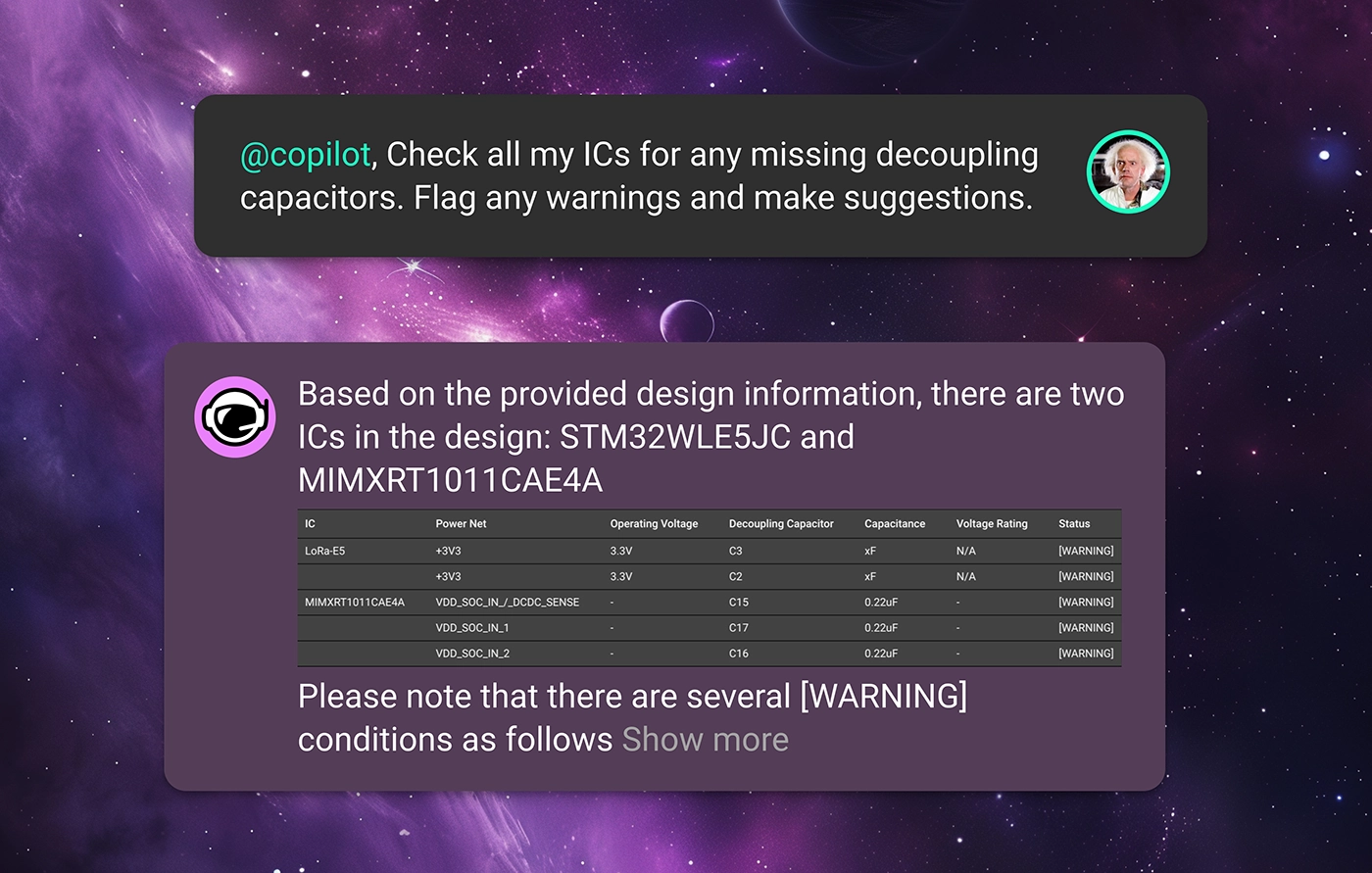
Copilot scrutinizes each IC pin in the schematic to ensure that a decoupling capacitor is present if required. It also verifies that each capacitor is appropriately rated for voltage and capacitance, ensuring that ICs operate within stable electrical environments without manual verification. Simply ask Copilot
For pins that require pull-up or pull-down resistors to maintain correct logic levels, Copilot ensures these resistors are present and correctly valued. This review helps maintain functional integrity throughout digital circuits, especially in complex designs. An example prompt might be

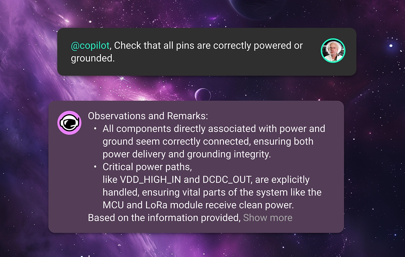
Copilot can check that all components requiring power are correctly connected to power sources and that all grounds are properly established. This ensures no component is left unpowered or incorrectly grounded, which is crucial for circuit functionality. Try asking
In each of these prompt examples, Copilot will read through component datasheets, check the context of your design, and provide expert-level feedback to your team. That way, errors can be caught earlier on and not propagate deeper into your design’s lifecycle.
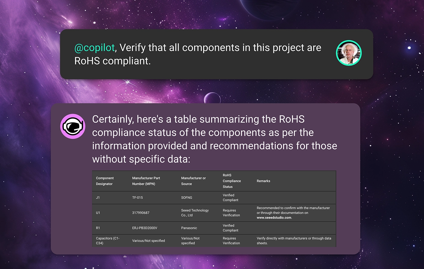
It’s one thing for your design to work, but, for a product to work reliably, it needs to be compliant with industry standards and regulations as well as your enterprise’s internal standards. This is often one of the biggest headaches in bringing a product to market.
For example, maybe the product team requires that your design achieves certain product certifications, meaning that there are rigid compliance standards to adhere to. Checking all the parts in your BOM to ensure that they meet your project requirements takes forever. In a situation like this, Copilot can ensure that the schematic design adheres to specific industry or environmental standards or regulations by checking component specifications and circuit configurations against predefined criteria. For example, ask Copilot
Or maybe your organization has strict design rules that should be adhered to concerning temperature ratings, power ratings, or derating characteristics. With Flux, every organization can define its specific design constraints using Copilot Templates. These templates are a place for your organization to define its project requirements so that Copilot can check your design against these rules to ensure that your design is meeting expectations.
With this knowledge, Copilot can read through datasheets to automatically verify that each component’s ratings are suitable for the intended application, reducing the risk of component failure under operational conditions. Just ask Copilot something like
With Copilot’s insight, you can ensure that your product reaches compliance with fewer design revisions, helping your team get the product to market faster.
Launching a product in the modern marketplace undoubtedly requires a design that is robust against supply chain volatility.
How many times have you finished a circuit design only to find out that one or more of the components has 10+ week lead times? When you’re trying to get a product to market, you can’t be at the whims of the post-COVID electronics supply chain.
Want to see if the parts in your BOM are all sourceable? Flux offers built-in integrations with industry-standard suppliers like Mouser, DigiKey, and LCSC to provide real-time pricing and availability data for all of the parts in your design.
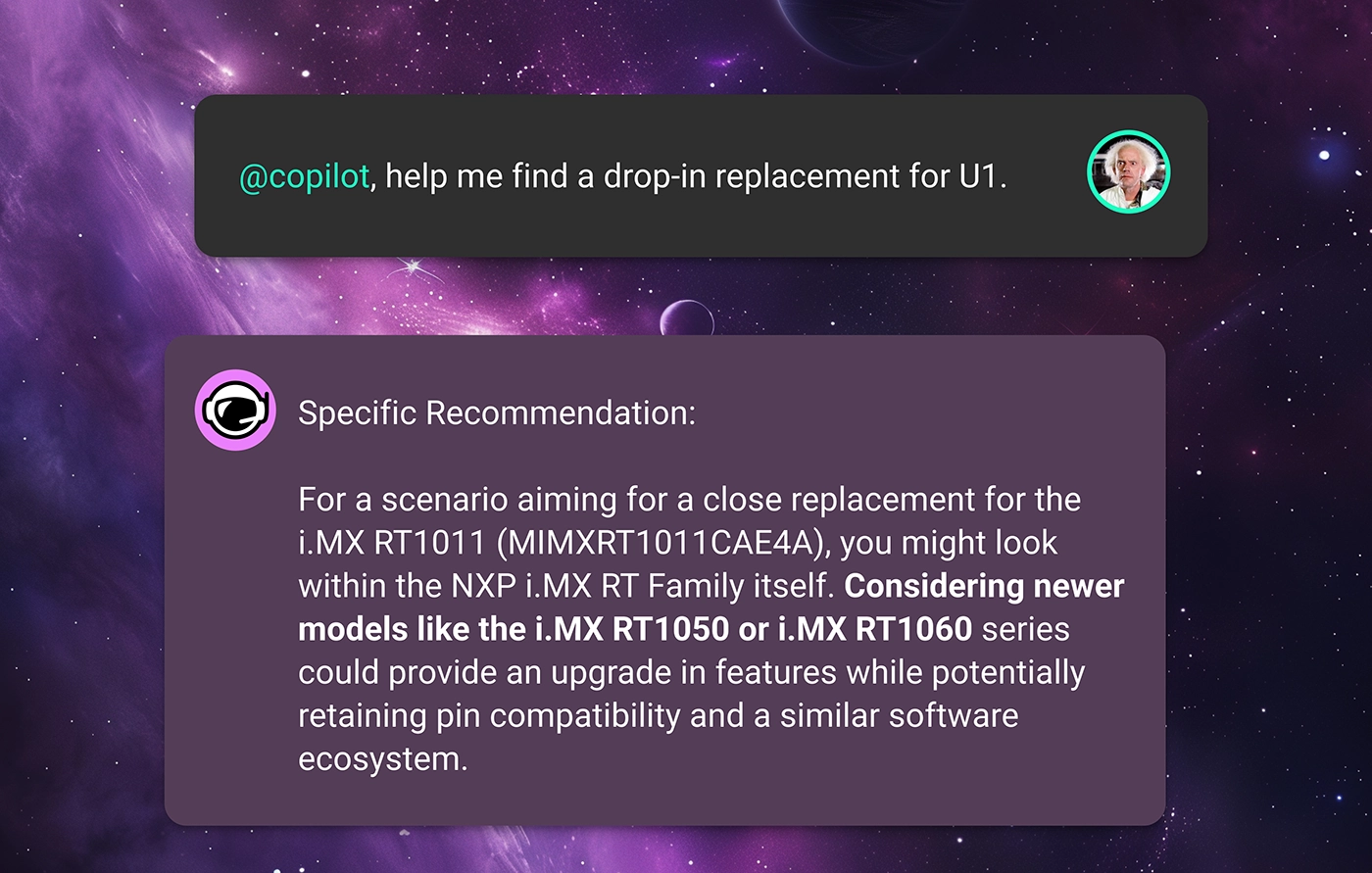
Then, if you're in need of component alternates, Copilot does the hard work for you. Thanks to our partnership with UltraLibrarian, Flux Copilot has access to thousands of the industry’s favorite parts right in the Flux Library. That means that Copilot can search through its database of components, comparing datasheets and availability data with your original part to find the most ideal drop-in alternates for your design. Ask copilot
Free your team from volatile supply-chain fluctuations and ship products on your own schedule.
This is only what’s possible with Copilot and AI today. In the future, we imagine a world where AI can do much more.
What if AI could continuously review your design in real time without being prompted? What if we could harness AI to make sure that there were no design errors ever, and first revision designs were good enough for production? We are building a future where faster and more continuous design reviews enable a completely new way of working, regardless of your platform or workflow.
At Flux, we believe that those “what-ifs” don’t have to be dreams. We are constantly working to make them a reality.
Want to learn more about how Flux’s AI can help revolutionize hardware design? Sign up for Flux today.
A comprehensive guide covering how schematic diagrams, symbols, schematic capture, and the schematic-to-PCB workflow form the foundation of electronics design, it's written for engineers and beginners alike.
From symbols and signal flow to schematic capture and PCB handoff — a complete guide for engineers and beginners alike.
If you're new to electronics, schematic design is probably one of the first things you'll run into and also one of the first things that makes you go "wait, what am I looking at?"
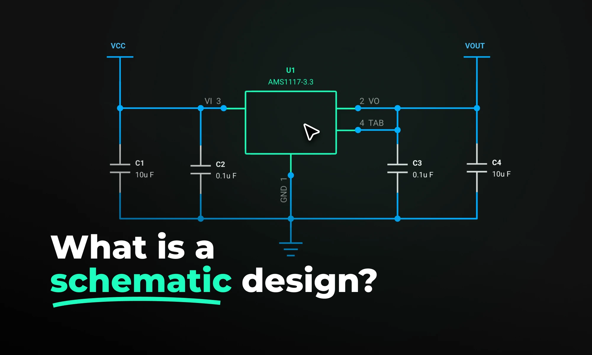
Simply put, schematic design is the process of mapping out an electronic circuit using symbols and lines before anything gets built. Think of it as the planning stage. Before a single component touches a board, engineers use a schematic to figure out every electrical connection, how components relate to each other, and where signals flow.
It's not about how the circuit looks physically. It's about how it works electrically. That distinction matters a lot, especially when you're just starting out.
A good schematic does three things: it shows how components connect through wires and nets, how parts depend on each other functionally, and which direction data, power, and control signals travel.
Catching mistakes at this stage is also way cheaper than catching them after a board has already been manufactured. And beyond that, a schematic becomes the shared language for everyone working on a project; engineers, firmware developers, and the manufacturing team all refer back to it.
A schematic diagram is the actual drawing, it's the visual output of the schematic design process. It uses standardized symbols to represent components and lines to show how they connect.
One thing that trips up a lot of beginners: a schematic diagram is not a picture of your circuit. A resistor symbol looks the same whether the physical part is tiny and surface-mounted or large and through-hole. The diagram doesn't care about size or shape, it only cares about electrical relationships.
Engineers typically read schematics left to right, top to bottom, with inputs on the left and outputs on the right. Once you get used to that flow, tracing how a circuit behaves becomes a lot more natural.
Worth keeping in mind: a schematic shows logical connectivity. A PCB layout shows physical placement and routing. Both matter, but they're answering different questions at different points in the design process.
Schematics use a visual language made up of standardized symbols, defined by standards like IEEE 315 and IEC 60617 so that any engineer anywhere can pick one up and read it.
You don't need to memorize all of them at once. Start with these six and you'll be able to follow most basic schematics:
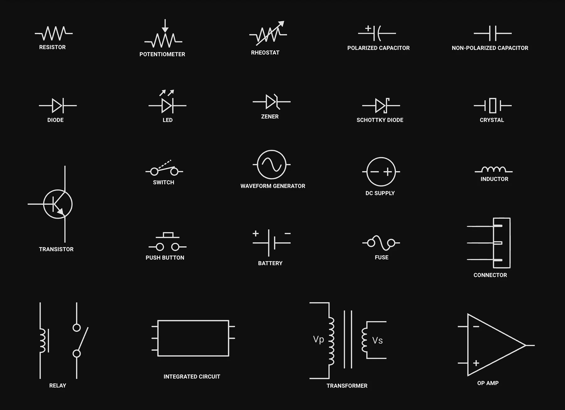
From there, you'll gradually pick up symbols for inductors, op-amps, MOSFETs, voltage regulators, connectors, and more. But these six are the foundation.
Once you have a circuit design in mind, you need to get it into a computer in a format that design tools can actually use. That process is called schematic capture.
You're essentially taking your idea — whether it's a sketch on paper or just a concept in your head — and turning it into a structured digital schematic using EDA (Electronic Design Automation) software. You place component symbols, draw connections between them, assign reference designators like R1, C1, U1, and fill in component values.
The result isn't just a drawing. It's machine-readable data that your toolchain can process downstream.
When you're done, the tool generates two things you'll use constantly:
Popular EDA tools for schematic capture include KiCad, Altium Designer, Cadence OrCAD, and newer browser-based platforms like Flux. Most modern tools also include real-time electrical rules checking (ERC), which automatically flags problems like unconnected pins, missing power references, or conflicting net names before a designer moves to layout.
The general flow goes: Schematic capture → ERC validation → netlist export → PCB layout → design rule check (DRC) → Gerber file generation → manufacturing. Get something wrong early and it ripples through everything downstream.
Ready to start your first schematic? Follow Flux step-by-step guide to designing your first project. Start your first schematic in Flux.
People often use "schematic" and "PCB layout" interchangeably, but they're really two separate things — and confusing them is a common beginner mistake.
The short version: a schematic is logical, a PCB layout is physical.
A good way to think about it: if the schematic is the wiring diagram of a building's electrical system, the PCB layout is the construction blueprint — showing exactly where cables run through the walls, how far apart conduits need to be, and which breakers connect where.
Neither replaces the other. A clean schematic doesn't guarantee your board will be manufacturable, and a beautifully routed PCB means nothing if the underlying schematic has a wiring error.
That said, the gap between schematic and finished layout is narrowing fast. Flux AI Auto-Layout feature lets engineers go from a verified schematic to a routed PCB with a single click, automatically placing components (already in beta), routing traces, prioritizing critical power paths, and delivering results clean enough to manufacture with minimal cleanup. Powered by reinforcement learning, it's a fundamentally different approach to PCB layout, and a glimpse at where the entire discipline is heading.
Even engineers who've been doing this for years make schematic mistakes. The tricky part is that some of them don't show up until the board comes back from fabrication, which is an expensive way to find out something went wrong.
Here are the ones worth watching out for:
With most traditional EDA tools like KiCad, Altium Designer, Cadence OrCAD, running an ERC is a manual step, it's something you remember to do when you think you're done, and hope you didn't miss anything in between.
In Flux handles this differently: ERC runs automatically in the background as you design, so issues get flagged in real time before they have a chance to pile up.
For a long time, schematic design meant installing heavyweight desktop software, managing licenses, and working in isolation. Tools like Altium Designer and Cadence Allegro are good, but they were built for a world where hardware teams sat in the same office.
That world has changed. Teams are distributed, timelines are shorter, and the expectation is that design tools should work the way modern software does, in the browser, collaboratively, without friction.
Hardware design is moving in the same direction software development did a decade ago, toward tools that are faster, more collaborative, and less painful to use. The days of emailing locked design files are numbered.