Flux Blog

News, resources, and company updates

Meet Files: AI-Native Project Documentation

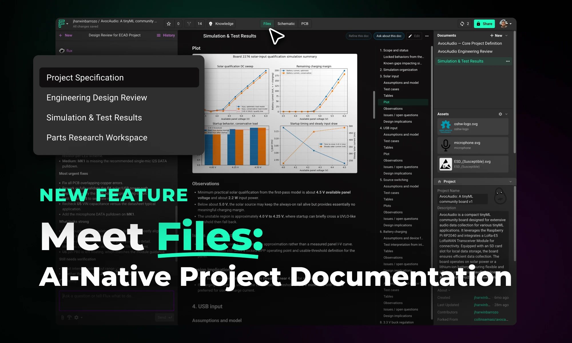
Files is a new top-level tab in Flux projects that centralizes all project documentation, including specs, uploaded assets, generated outputs, and project descriptions, in one place. This gives Flux full access to your project context, enabling better outputs, continuity across sessions, and easier team collaboration.

|
April 16, 2026
Thank you! Your submission has been received!
Oops! Something went wrong while submitting the form.
RP2350 A4 Stepping: Why Raspberry Pi Pico’s Latest Upgrade Changes Everything

RP2350 A4 Stepping: Why Raspberry Pi Pico’s Latest Upgrade Changes Everything

RP2350 A4 fixes GPIO bug, hardens security, adds 5 V tolerance and on-chip flash. See why every Pico project should migrate.

What Is the RP2350 A4 Stepping?

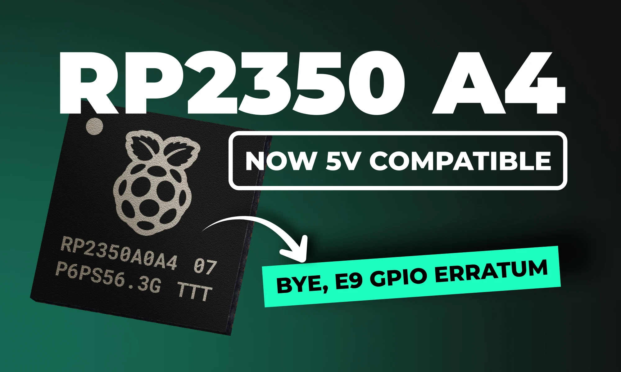
The RP2350 A4 stepping is the latest iteration of Raspberry Pi's powerful dual-core MCU, designed to correct significant hardware and security issues identified in earlier versions (particularly the A2 stepping). This update provides comprehensive improvements, delivering both enhanced security and optimized hardware performance, making it a must-have upgrade for serious developers and embedded systems designers alike.

If you're connecting the RP2350 to retro computing hardware, there's good news: after extensive testing, the RP2350 is now officially 5V tolerant!

{{underline}}

Can My Current Pico Projects Run on the New A4 Stepping?

Absolutely! Because A4 is a pin-compatible, drop-in replacement, your existing Pico designs work right away, often with nothing more than a rebuild on the latest SDK. Here are four examples you can migrate today:

  1. Pico Smart Automation Controller – A DIY home-automation hub that enables intelligent control for sensors, relays, and devices.
  2. Pico Macro Keyboard – A customizable USB HID keypad a.k.a macro pad built using the Raspberry Pi Pico 2.
  3. Avocaudio – Tiny Community Audio Board – A tinyML board designed for extensive audio data collection across various tinyML applications.
  4. Raspberry Pi Pico 2 Shield Template – A ready-made “shield” PCB that mirrors the exact footprint and pin order of the Pico 2, much like an Arduino shield.

{{upsell-project}}

{{underline}}

How Can I Tell If I Have the A2 or A4 Stepping?

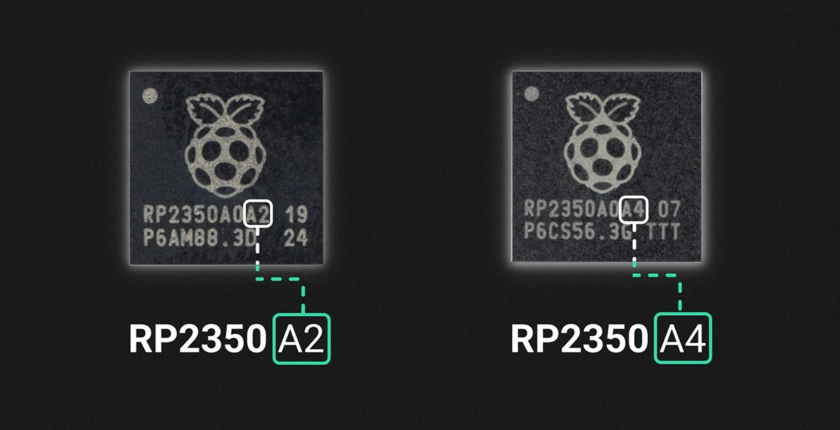
You can identify the stepping version from the marking on the top surface of the chip, as illustrated below.

{{underline}}

Do Pinouts Change with the RP2350 A4 Stepping?

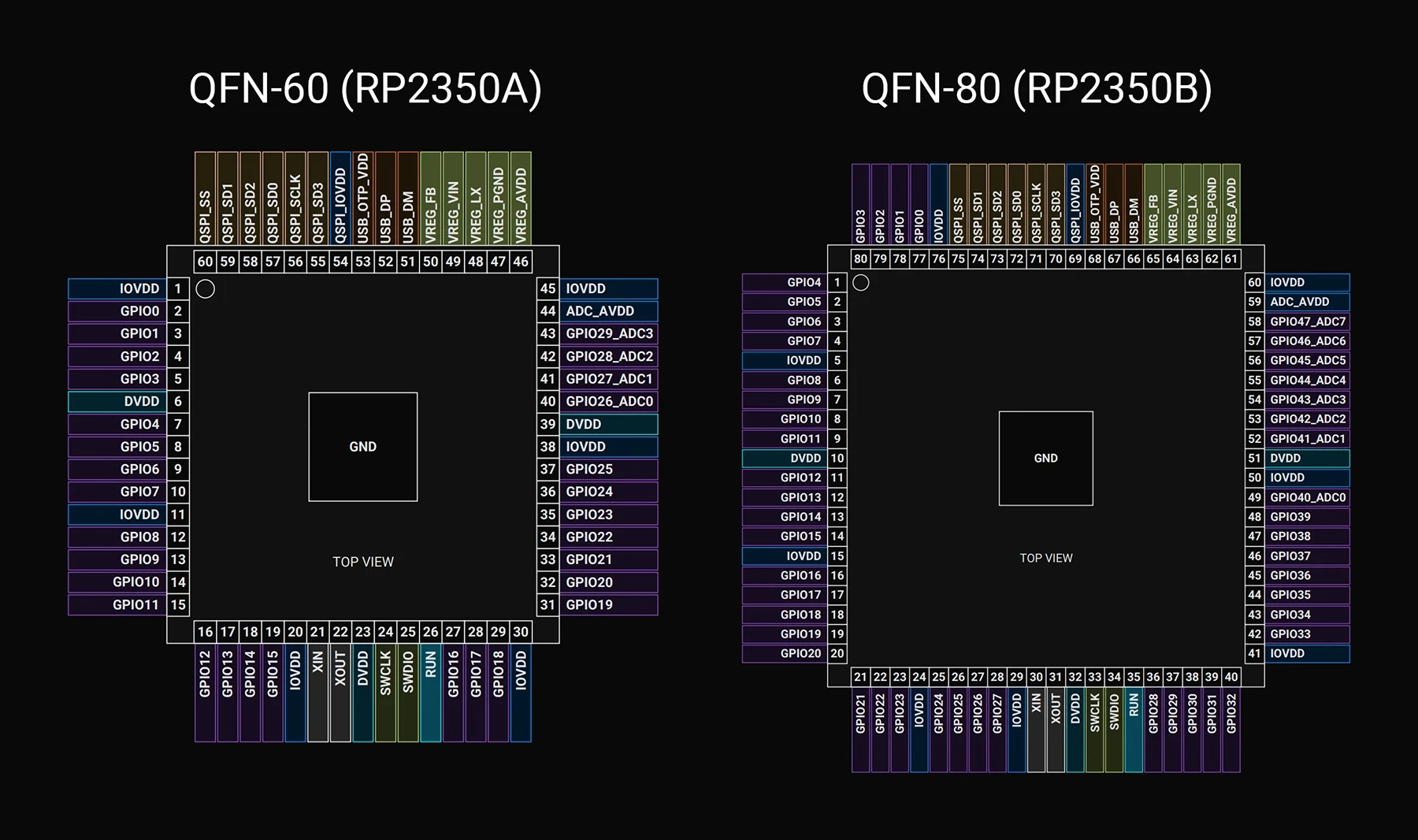
No, great news for hardware engineers! The pin configuration and layout of the RP2350 A4 stepping remain identical to earlier versions, making it a perfect drop-in replacement. You can upgrade existing hardware designs without any modifications to your PCB layouts.

Below, I've included a detailed pinout mapping for quick reference.

GPIO Pins

| Name | QFN-60 | QFN-80 | Type | Power Domain | Description | | :--- | :---: | :---: | :--- | :--- | :---: | | GPIO0 | 2 | 77 | Digital IO (FT) | IOVDD | User IO | | GPIO1 | 3 | 78 | Digital IO (FT) | IOVDD | User IO | | GPIO2 | 4 | 79 | Digital IO (FT) | IOVDD | User IO | | GPIO3 | 5 | 80 | Digital IO (FT) | IOVDD | User IO | | GPIO4 | 7 | 1 | Digital IO (FT) | IOVDD | User IO | | GPIO5 | 8 | 2 | Digital IO (FT) | IOVDD | User IO | | GPIO6 | 9 | 3 | Digital IO (FT) | IOVDD | User IO | | GPIO7 | 10 | 4 | Digital IO (FT) | IOVDD | User IO | | GPIO8 | 12 | 6 | Digital IO (FT) | IOVDD | User IO | | GPIO9 | 13 | 7 | Digital IO (FT) | IOVDD | User IO | | GPIO10 | 14 | 8 | Digital IO (FT) | IOVDD | User IO | | GPIO11 | 15 | 9 | Digital IO (FT) | IOVDD | User IO | | GPIO12 | 16 | 11 | Digital IO (FT) | IOVDD | User IO | | GPIO13 | 17 | 12 | Digital IO (FT) | IOVDD | User IO | | GPIO14 | 18 | 13 | Digital IO (FT) | IOVDD | User IO | | GPIO15 | 19 | 14 | Digital IO (FT) | IOVDD | User IO | | GPIO16 | 27 | 16 | Digital IO (FT) | IOVDD | User IO | | GPIO17 | 28 | 17 | Digital IO (FT) | IOVDD | User IO | | GPIO18 | 29 | 18 | Digital IO (FT) | IOVDD | User IO | | GPIO19 | 31 | 19 | Digital IO (FT) | IOVDD | User IO | | GPIO20 | 32 | 20 | Digital IO (FT) | IOVDD | User IO | | GPIO21 | 33 | 21 | Digital IO (FT) | IOVDD | User IO | | GPIO22 | 34 | 22 | Digital IO (FT) | IOVDD | User IO | | GPIO23 | 35 | 23 | Digital IO (FT) | IOVDD | User IO | | GPIO24 | 36 | 25 | Digital IO (FT) | IOVDD | User IO | | GPIO25 | 37 | 26 | Digital IO (FT) | IOVDD | User IO | | GPIO26_ADC0 | 40 | | Digital IO / Analog | IOVDD / ADC_AVDD | User IO or ADC input | | GPIO27_ADC1 | 41 | | Digital IO / Analog | IOVDD / ADC_AVDD | User IO or ADC input | | GPIO28_ADC2 | 42 | | Digital IO / Analog | IOVDD / ADC_AVDD | User IO or ADC input | | GPIO29_ADC3 | 43 | | Digital IO / Analog | IOVDD / ADC_AVDD | User IO or ADC input | | GPIO26 | | 27 | Digital IO (FT) | IOVDD | User IO | | GPIO27 | | 28 | Digital IO (FT) | IOVDD | User IO | | GPIO28 | | 36 | Digital IO (FT) | IOVDD | User IO | | GPIO29 | | 37 | Digital IO (FT) | IOVDD | User IO | | GPIO30 | | 38 | Digital IO (FT) | IOVDD | User IO | | GPIO31 | | 39 | Digital IO (FT) | IOVDD | User IO | | GPIO32 | | 40 | Digital IO (FT) | IOVDD | User IO | | GPIO33 | | 42 | Digital IO (FT) | IOVDD | User IO | | GPIO34 | | 43 | Digital IO (FT) | IOVDD | User IO | | GPIO35 | | 44 | Digital IO (FT) | IOVDD | User IO | | GPIO36 | | 45 | Digital IO (FT) | IOVDD | User IO | | GPIO37 | | 46 | Digital IO (FT) | IOVDD | User IO | | GPIO38 | | 47 | Digital IO (FT) | IOVDD | User IO | | GPIO39 | | 48 | Digital IO (FT) | IOVDD | User IO | | GPIO40_ADC0 | | 49 | Digital IO / Analog | IOVDD / ADC_AVDD | User IO or ADC input | | GPIO41_ADC1 | | 52 | Digital IO / Analog | IOVDD / ADC_AVDD | User IO or ADC input | | GPIO42_ADC2 | | 53 | Digital IO / Analog | IOVDD / ADC_AVDD | User IO or ADC input | | GPIO43_ADC3 | | 54 | Digital IO / Analog | IOVDD / ADC_AVDD | User IO or ADC input | | GPIO44_ADC4 | | 55 | Digital IO / Analog | IOVDD / ADC_AVDD | User IO or ADC input | | GPIO45_ADC5 | | 56 | Digital IO / Analog | IOVDD / ADC_AVDD | User IO or ADC input | | GPIO46_ADC6 | | 57 | Digital IO / Analog | IOVDD / ADC_AVDD | User IO or ADC input | | GPIO47_ADC7 | | 58 | Digital IO / Analog | IOVDD / ADC_AVDD | User IO or ADC input |

QSPI Pins

| Name | QFN-60 | QFN-80 | Type | Power Domain | Reset | Description | | :--- | :---: | :---: | :--- | :--- | :---: | :--- | | QSPI_SD3 | 55 | 70 | Digital IO | QSPI_IOVDD | Pull-Up | QSPI data | | QSPI_SCLK | 56 | 71 | Digital IO | QSPI_IOVDD | Pull-Down | QSPI clock | | QSPI_SD0 | 57 | 72 | Digital IO | QSPI_IOVDD | Pull-Down | QSPI data | | QSPI_SD2 | 58 | 73 | Digital IO | QSPI_IOVDD | Pull-Up | QSPI data | | QSPI_SD1 | 59 | 74 | Digital IO | QSPI_IOVDD | Pull-Down | QSPI data | | QSPI_SS | 60 | 75 | Digital IO | QSPI_IOVDD | Pull-Up | QSPI chip select / USB BOOTSEL |

Crystal Oscillator Pins

| Name | QFN-60 | QFN-80 | Type | Power Domain | Description | | :--- | :---: | :---: | :--- | :--- | :--- | | XIN | 21 | 30 | Analogue (XOSC) | IOVDD | Crystal oscillator; XIN may also be driven by a square-wave source | | XOUT | 22 | 31 | Analogue (XOSC) | IOVDD | Crystal oscillator |

Misc Pins

| Name | QFN-60 | QFN-80 | Type | Power Domain | Reset | Description | | :--- | :---: | :---: | :--- | :--- | :---: | :--- | | RUN | 26 | 35 | Digital In (FT) | IOVDD | Pull-Up | Chip enable / reset_n | | SWCLK | 24 | 33 | Digital In (FT) | IOVDD | Pull-Up | Serial Wire Debug clock | | SWDIO | 25 | 34 | Digital IO (FT) | IOVDD | Pull-Up | Serial Wire Debug data |

USB Pins

| Name | QFN-60 | QFN-80 | Type | Power Domain | Description | | :--- | :---: | :---: | :--- | :--- | :--- | | USB_DP | 52 | 67 | USB IO | USB_QTP_VDD | USB Data +; 27 Ω series resistor required for USB operation |

{{underline}}

What’s New in the RP2350 A4 Stepping?

This stepping addresses several critical issues and introduces highly requested features:

  • GPIO Leakage Bug Fixed: Resolves the notorious RP2350 erratum 9, removing unwanted current leakage on GPIO pins. As a result, external resistors are no longer required to pull inputs low, though they may safely be retained in existing designs.
  • Enhanced Security: Addresses boot ROM exploits, OTP corruption, glitch vulnerabilities, and provides hardened AES encryption for secure applications.
  • Integrated Flash Versions: Introduction of RP2354A/B variants with built-in 2 MB flash, simplifying hardware design and lowering production complexity.
  • Official 5V GPIO Tolerance: Easier interfacing with legacy and retro-computing hardware without needing additional level shifting.

{{underline}}

Why Does the A4 Stepping Matter to You?

  • Goodbye GPIO Leakage. No more worrying about external workarounds, your designs become simpler, cheaper, and more reliable.
  • Stronger Security from the Ground Up. Hardened security improvements protect your products from known vulnerabilities, ensuring safer deployments, particularly important in IoT, industrial, and sensitive embedded projects.
  • Simplified Hardware Design. The RP2354 integrated-flash variant significantly reduces design complexity, saving PCB space and manufacturing costs.
  • Wider Compatibility. Official support for 5 V GPIO levels unlocks compatibility with more devices, sensors, and legacy systems without extra complexity.

{{underline}}

Will the A2 stepping be discontinued?

Raspberry Pi already stopped manufacturing the A2 stepping, shifted all production exclusively to A4, and removed remaining A2 inventory from distribution channels. The A4 stepping is a direct, drop-in replacement for A2, so you shouldn't encounter any issues transitioning to the newer version.

{{underline}}

How Can You Upgrade to the RP2350 A4 Stepping?

Follow these simple steps to leverage the power of RP2350 A4 in your Raspberry Pi Pico projects:

  1. Update your Pico SDK to version 2.1.0 or newer (recommended: 2.2.0).
  2. Rebuild your firmware using the latest SDK to ensure compatibility and utilize new security features.
  3. Switch to RP2350 A4 stepping hardware fully compatible with existing designs but with improved security and reliability.

{{underline}}

Availability and Pricing

  • RP2350A/B A4 Stepping: Now widely available through official Raspberry Pi distributors.
  • RP2354 Integrated Flash Variants: Available soon at around $1.30 to $1.40 per chip, simplifying your designs and saving costs.

{{underline}}

Final Thoughts

The RP2350 A4 stepping significantly upgrades the potential of Raspberry Pi Pico-based designs. Enhanced security, hardware reliability, simpler designs, and broad compatibility make this stepping a turning point for professional and hobbyist projects alike.

Explore our Featured Projects page to discover more Raspberry Pi projects and fresh ideas that will jump-start your next hardware prototype.

{{upsell-project}}

|
August 7, 2025
AI Auto-Layout Just Got Smarter

AI Auto-Layout Just Got Smarter

Today, we’re excited to share our Summer Update to Flux AI Auto‑Layout, a collection of improvements designed to make one‑click PCB routing more reliable, transparent, and adaptable to your real‑world workflows.

This update is a set of pragmatic steps toward our vision of Auto‑Layout as your trusted routing assistant. Here's what's improved:

  • Prioritize Nets with Net Types—add a ‘Net Type’ rule manually to your net properties or let Flux do it for you.
  • Relaxed Clearance—results are now cleaner, more manufacturable, and more reliable.
  • Protected Polygons—small copper polygons will be protected from trace intrusions while larger split planes still work as you need them.

Auto‑Layout still works best when guided by thoughtful placement, clear net names, and rulesets—but now it’s a more predictable, collaborative partner in your design process.

Deep Dive Inside the Summer Update

1. Net Priority: Routing in Smart Sequence

Classify your nets into seven priority buckets—High Speed, Analog, Power, Medium Speed, Low Speed, Uncertain, and Ground—and Auto‑Layout will route them in that exact order. Flux will infer the Net Type of each net in your design, but you can check and change the inference by selecting a net and altering the Net Type property.

High‑speed nets go first.
Analog nets get their own quiet lanes.
Power nets find robust copper paths.

This helps ensure your most sensitive signals aren’t forced into awkward detours, delivering a draft layout that mirrors your own routing instincts.

2. Relaxed Clearance: Cleaner Looks over Absolute Shortest Paths

Previous versions of Flux Auto‑Layout often scrunched traces up against neighboring pads or nets to minimize length. We’ve softened that bias so traces now favor open board areas—even if they grow a few mils longer.

  • Cleaner, more “organic” routing reminiscent of a hand‑routed board
  • Improved manufacturability, with wider gaps reducing solder‑bridge risk
  • Slightly longer traces, so plan ahead if you’re in a length‑critical design

Think of it as trading a few extra mils for a huge win in clarity and yield.

3. Protected Polygons: Respect Your Copper

AI Auto-Layout, now, any polygon covering less than 30% of the board area is automatically protected from wires and vias unless you explicitly disable that rule.

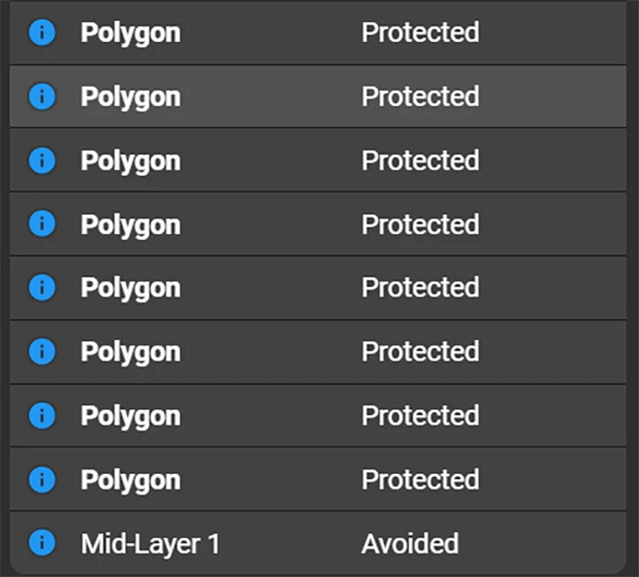
Earlier, Auto‑Layout could inadvertently slice through copper pours—especially smaller ones. Now, any polygon covering less than 10% of the board area is automatically protected from wires and vias unless you explicitly disable that rule.

  • No more surprise pour “islands” in your Gerbers
  • Seamless split‑plane support for advanced power or ground schemes
  • Greater peace of mind when working with critical copper fills

How to Make the Most of Auto‑Layout Today

Auto‑Layout shines when you guide it. Here’s a quick workflow that scales from beginners to power users:

  1. Thoughtful Placement. Follow general component placement best practices or watch our video on the placement tips. Group connectors, oscillators, and regulators close to their targets. Leave clear channels for high‑speed and analog nets.
  2. Classify Your Nets
  3. Define Zones & Rulesets. Draw Zones around antennas or heat‑sensitive areas. Create selector‑based rules for common net groups to speed up future projects.
  4. Choose a Workflow
    • Full‑Board Route: One click, start to finish.
    • Hybrid Approach: Pre‑route critical nets, then finish with Auto‑Layout.
    • Placement Check: Run Auto‑Layout early to catch crowded components.

Who Benefits Most

  • Beginners gain confidence by seeing a professionally routed board come together in minutes—while learning best practices from the resulting layouts.
  • Intermediate & Advanced Users offload repetitive low‑critical nets (LED arrays, sensor grids) and focus manual effort on the tricky high‑speed or power sections.

Either way, Auto‑Layout becomes a force multiplier—not a replacement for your expertise.

What’s Next

This Summer Update is a milestone on our roadmap. In the coming months, expect deeper AI understanding of complex topologies, tighter integration with constraint management, and collaborative features that let teams iterate on one layout in real time.

Your feedback is the compass that guides us. Try the Summer Update today—log in, hit “Auto‑Layout”, and tell us where it shined or stumbled via in‑app feedback or our Slack channel. Together, let’s make routing the easiest part of hardware design.

|
July 31, 2025
Introducing Copilot Knowledge Base for Flux Engineers

Introducing Copilot Knowledge Base for Flux Engineers

In this post, we’ll show you exactly how to unlock the power of Flux Copilot for yourself: from writing rock-solid triggers to scoping entries at the project, user, and system levels.

Today, EE teams using Flux are already leveraging Knowledge Base to encode their professional know-how—things like project constraints, personal style guides, and industry-vetted best practices—directly into Copilot. In this post, we’ll show you exactly how to unlock that power for yourself: from writing rock-solid triggers to scoping entries at the project, user, and system levels.

Don’t miss out on this opportunity. Take these tips and tricks, apply them today, and watch Copilot transform from a tool into a teammate who thinks—and designs—just like you.

With Knowledge Base, we capture insights at three levels:

  • Project-level: Requirements, calculations, and architecture choices unique to your current board
  • User-level: Your personal style guides, part-family preferences, and schematic conventions
  • System-level: Flux-curated best practices and EE-expert recommendations that benefit everyone

Let’s dive into how it works, why it matters, and—most importantly—how you can craft entries that make Copilot truly think like you.

1. How the Knowledge Base Works & Why It Matters

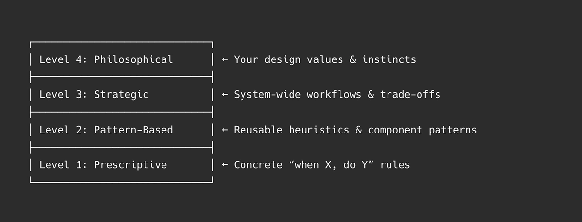
Flux Copilot’s Knowledge Base entries can be thought of at four levels—from narrow rules to high-level mindsets. When you prompt Copilot, it performs a semantic search, a search that uses sentence structure similarity to find matches , then weaves the most relevant guidance into its reasoning.

Semantic Triggers

Every entry begins with a “use when” phrase. Copilot uses vector search, finding similar items in a dataset by comparing their numerical vector representations (embeddings) instead of relying on exact keyword matches, to match your prompt to the right piece of advice based on semantic similarity.

Context Injection

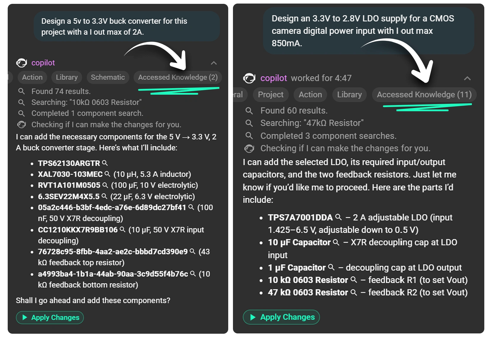
When you ask Copilot, for example, to generate a buck-converter schematic, it retrieves relevant entries—your project’s input-voltage constraint, your favorite inductor series, or a net-naming rule—and seamlessly injects that context into its response.

Three-Tier Scope

  • Project: Active only within the board you’re editing
  • User: Applies across all your Flux projects
  • System: Flux-approved, peer-reviewed EE best practices

Impact & Examples of Good Results

2. Crafting Effective “Use When” Statements

The use when is the most critical piece of any entry—it tells Copilot when to apply your guidance, based on semantic similarity, not just keywords. If this is off, your advice will never—or always—fire.

  • Keep it short (6–9 words)
  • Lead with your key concept (noun or verb first)
  • Be 100% true to the context you’re capturing
  • Use action verbs (e.g. designing, validating, calculating)
  • Broad vs. Specific:
    • Broad: use when: filtering power rails
    • Specific: use when: designing Pi filters for multi stage power rail
Pro Tip: After Copilot suggests a “use when,” refine it immediately. A small tweak—“for high-speed analog filters” instead of just “for filters”—can mean perfect recall instead of irrelevant noise.

3. Project-Level Knowledge (with Examples)

Project-level entries store all the details that make your current board design one-of-a-kind. They include specific requirements (like voltage tolerances), physical or thermal constraints, chosen topology decisions, and any reference calculations you’ve performed. By capturing the reasoning behind each architectural choice, Copilot can apply context-aware guidance tailored solely to this project. This prevents generic suggestions from slipping through and keeps your design aligned with its unique specifications.

  • Design requirements
    Example:
use when: selecting temperature sensitive components
content: this design is exposed to temperatures of -10 F to 110 F on a Northeastern US State yearly temperature cycle.
  • Design constraints
    Example:
use when: board size constraints
content: Ensure components selected are optimized for a wearable device sized board.
  • Architecture decisions
    Example:
use when: designing a power distribution network
content: Optimize for small size and effeciency for each power component.

4. User-Level Knowledge (with Examples)

User-level entries capture your personal design preferences, workflows, and preferred subcircuit patterns so that Copilot reflects how you work. They let you encode procedural steps—like your favorite LDO selection or filter-design process—directly into Copilot’s memory. With these entries, Copilot adopts your schematic conventions, part choices, and step-by-step habits, producing outputs that feel tailored and familiar. In effect, it transforms Copilot from a generic assistant into one that thinks and advises just as you would.

  • Procedural instructions
    LDO selection
use when: LDO selection process
content: When selecting an LDO, follow a structured four-step workflow: screen basic parameters, filter performance (PSRR, noise), prioritize the key metric, and check optional features.
  • Filter design
use when: filter design process
content: When formalizing filter design, begin with clear specs (ripple, f_c, f_s, attenuation) and then proceed with topology selection, component choice, simulation, and disciplined prototyping.
  • Schematic style guidelines
    Example 1:
use when: naming nets for differential pairs  
content: Prefix with SIG_DP_ or SIG_DM_ and suffix with _N/_P for polarity clarity.  
  • Example 2:
use when: naming nets with series resistors
content: Add a suffix _R to the name of the incoming net to the resistor and use it for the outgoing net name.  
  • Tips for specialized circuits
    Example:
use when: designing op-amp instrumentation amplifiers  
content: Add 10 Ω series resistors on each input to decouple source capacitance.  
  • Component-specific instructions
    Example:
use when: using TI SN65HVD230 CAN transceiver  
content: Place 120 Ω termination resistors close to the transceiver and add 0.1 µF decoupling on VCC.

5. System-Level Knowledge (How We Build It)

Our EE team crafts system entries with the highest rigor—so every user benefits from vetted best practices.

  1. Source & Draft
    • Extracted from whitepapers, application notes, and our expert’s experience
  2. Peer Review
    • Our team of senior engineers validate technical accuracy and remove any vendor bias
  3. Semantic Validation
    • We test “use when” triggers against hundreds of prompt variations to ensure relevance
Note: Every word is chosen deliberately—“use when” must be as true as the “content” it triggers.

6. Managing Your Knowledge Base

As your KB grows, keep it relevant and helpful by:

  1. Watching Scopes
    • ✅ Don’t mix project-specific facts into user-level entries
    • Edit user entries: Profile → Knowledge → User Knowledge
    • Edit project entries: Project → Knowledge → Project Knowledge
  2. Monitoring Performance
    • Hit the 👎 thumbs-down when Copilot misapplies an entry or forms a bad response
    • Identify entries causing loops: “Why does it always suggest the same value for an inductor?”
  3. Signs of Harmful Entries
    • Over-fixation: Copilot insists on one solution for every design
    • Inaccuracies: Obvious part-selection errors or illogical guidance
  4. Regular Audits
    • Periodically review and prune outdated or narrow entries
    • Elevate broadly useful user entries to system level for team-wide benefit

Start Building Your KB Today

Adding your knowledge to Copilot doesn’t just make it smarter—it makes you faster, more consistent, and more confident. Open Flux Copilot, watch for that “Knowledge Suggestion” button in the response, and begin teaching your AI teammate how you design. Over time, your Knowledge Base becomes a living encyclopedia of your best practices—project by project, decision by decision.

|
July 18, 2025
Less Clicking, More Building: The New AI-First UI

Less Clicking, More Building: The New AI-First UI

This update brings more than just polish—it’s the foundation for a faster, more fluid design experience, built around the way Copilot is used today and the way we see it evolving tomorrow.

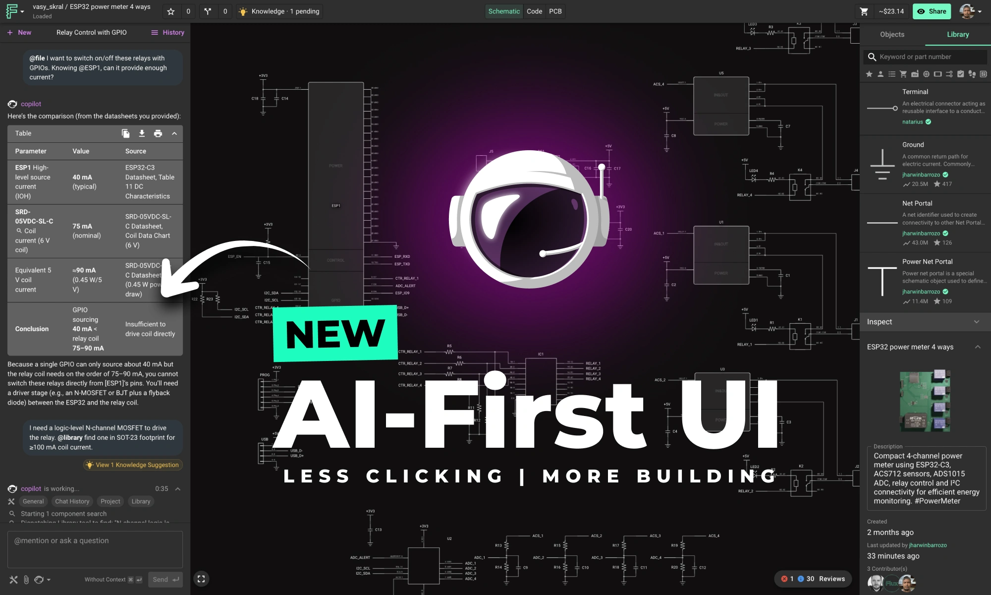
Copilot is evolving fast—from a helpful assistant to a true design partner. Today, it can generate smart BOMs, place components in your schematic, suggest replacements, and even learn how you design through custom knowledge base entries. For many workflows, it’s already the fastest way to move your project forward.

But for Copilot to truly shine, the interface needs to get out of the way.

Until now, working with Copilot often meant bouncing between tabs—opening the object browser, toggling the Inspector, trying to remember where you saw something last. That’s friction. And friction slows down flow.

So we redesigned the layout to match how modern engineers work: with AI alongside them.

This update brings more than just polish—it’s the foundation for a faster, more fluid design experience, built around the way Copilot is used today and the way we see it evolving tomorrow.

What’s New in the Layout

  • Copilot is now docked on the left, where your prompts and questions typically begin.
  • Part library and object tree are now placed on the right, where a collapsible Inspector sits alongside them, giving you immediate access to the tools you reference most.
  • The chat interface has been redesigned for clarity, with a clean left-right layout: your messages appear on the right in blue bubbles, Copilot responses appear on the left. The conversation is prioritized, while actions and metadata recede, only showing up at the right times.
  • Prompt suggestions only appear after the most recent Copilot message, keeping threads focused and uncluttered.
  • When Copilot is formulating a response, it shows context, tools, and reasoning inline—then collapses them into the message header once the reply streams in. You can always expand to see what it used.

This setup reduces interface friction—less tab switching, less mouse travel, and more continuous momentum throughout your workflow. The new layout improves the core ECAD experience too—placing the object browser and Inspector side-by-side, making it easier to inspect and modify your design at a glance. Less jumping around. More flow.

Faster Workflows with Copilot

This isn’t just a visual update—it’s a real improvement in how you work. With the new layout, these tasks now feel dramatically smoother:

  • Generate a block diagram - Simply have a conversation with Copilot about what you intend to build using as much information as you know. Copilot can use your requirements and constraints to explore many different architectural ideas and variations quickly.
  • BoM Generation - Just describe what you're building in natural language. Copilot will recommend key components by searching the parts library, reading datasheets, and applying its internal knowledge.
  • Swap Parts Without Losing Context - Need to replace a part but keep key specs? Now you can use Copilot and the Inspector side-by-side. Describe the changes you need, and immediately browse recommended part properties.
  • Place Multiple Parts in Seconds - After generating a BOM, Copilot can now drop components directly into your schematic—no manual lookup required.
  • Teach Copilot How You Work - Add naming conventions, preferred parts, or layout rules to your knowledge base, and Copilot will start adapting—carrying your preferences across projects automatically.

Setting the foundation for the future

This update is more than just a layout shift. It reflects a core belief: AI isn’t just a feature—it’s becoming the interface. Looking ahead, we’re building toward a future where hardware design starts with a conversation. You’ll always have full control—nothing is hidden in a black box—but we envision a workflow where your ideas move from prompt to PCB through an intelligent, adaptable partner. Eventually, you may find yourself managing a team of AI collaborators, each handling part of the design process in parallel, all coordinated through natural language.

Try the New Layout Today

Flux is getting smarter, faster, and more intuitive—so you can spend less time managing tabs and more time designing boards. Whether you’re a first-timer or returning after a break, now’s the perfect moment to jump in.

👉 Open Flux and try the new Copilot-first layout today.

|
July 10, 2025
Smarter Copilot, Cleaner Layouts, Fewer Bugs

Smarter Copilot, Cleaner Layouts, Fewer Bugs

This month, we’re rolling out major upgrades to Flux Copilot’s reasoning, transparency, and layout performance—plus some crucial fixes and a big leap in modular design reliability.

🧠 Copilot just got a lot smarter

A few weeks ago, we launched Copilot Knowledge—a way for you to teach Copilot how you work. As you approve suggestions, they become part of your personal or project memory: vendor preferences, naming conventions, design rules, review checklists, and more.

The result? Faster decisions, fewer mistakes, and better suggestions without repeating yourself.

Now we’re introducing the next layer: System Knowledge. This is a shared, curated knowledge base built by our team of senior engineers—including folks from NASA and other top hardware teams. They’re constantly encoding real-world insights, best practices, and edge cases that help Copilot make smarter choices across the board.

By combining your personal knowledge with system-wide expertise, Copilot becomes more responsive, more accurate, and more relevant to how modern hardware actually gets built. It now blends tribal wisdom with engineering logic to solve problems that used to require manual intervention—or years of experience.

Want to shape what Copilot knows? Hit us up in Slack or Canny with ideas—naming conventions, routing strategies, design rules. The more we share, the better it gets for everyone.

📦 Copilot now shows its work

No more black box. Copilot now gives real-time feedback as it processes part selections and schematic requests.

You’ll see a live execution trace—how it searches, filters, ranks, and substitutes. It’s like watching a checklist unfold in real time. Whether you’re validating a part or building a schematic from scratch, Copilot shows exactly what it’s doing, and why.

⚡ Speed and precision upgrades

Alongside transparency, we’ve made core performance improvements to Copilot’s part-selection engine:

  • 2–3× faster library searches
  • More accurate MPN targeting
  • More consistent behavior when adding parts in bulk

These changes reduce wait time, improve reliability, and keep your momentum flowing during schematic design.

🔝 Auto-Layout improvements

Thanks to your feedback, AI Auto-Layout just got a serious upgrade:

  • Supports your full via config, including microvias
  • Avoids awkward trace angles
  • Smarter pad exit direction logic
  • Better handling for castellated edge pins

These changes make Auto-Layout results cleaner, more production-ready, and easier to tweak.

🔜 Coming soon to Auto-Layout

We’re not done yet. Here’s what’s coming next:

  • Differential pair routing—even when pins aren’t adjacent
  • Smarter net spacing when layout allows
  • Routing prioritization based on net type (power, clock, etc.)

🧱 Module reliability fixes

We resolved a core issue where polygons broke inside modules—restoring full support for airwire and copper DRC checks in modular designs. Now your modules behave predictably from design to fab.

Try it out

All of this is live now—log in to Flux and give the latest updates a spin. As always, keep the feedback coming. We’re building Flux Copilot with you.

|
June 26, 2025
Crosstalk, Reflections, and the Real Challenges of Signal Integrity

Crosstalk, Reflections, and the Real Challenges of Signal Integrity

This post explains key signal integrity issues like crosstalk and reflections in PCBs and offers simple layout tips to avoid them. A free guide is included.

You followed the datasheet, double-checked the footprints, and kept your traces clean. But the moment your board hits production, there’s noise on the lines, your timing margins collapse, or worse: the board doesn’t pass compliance.

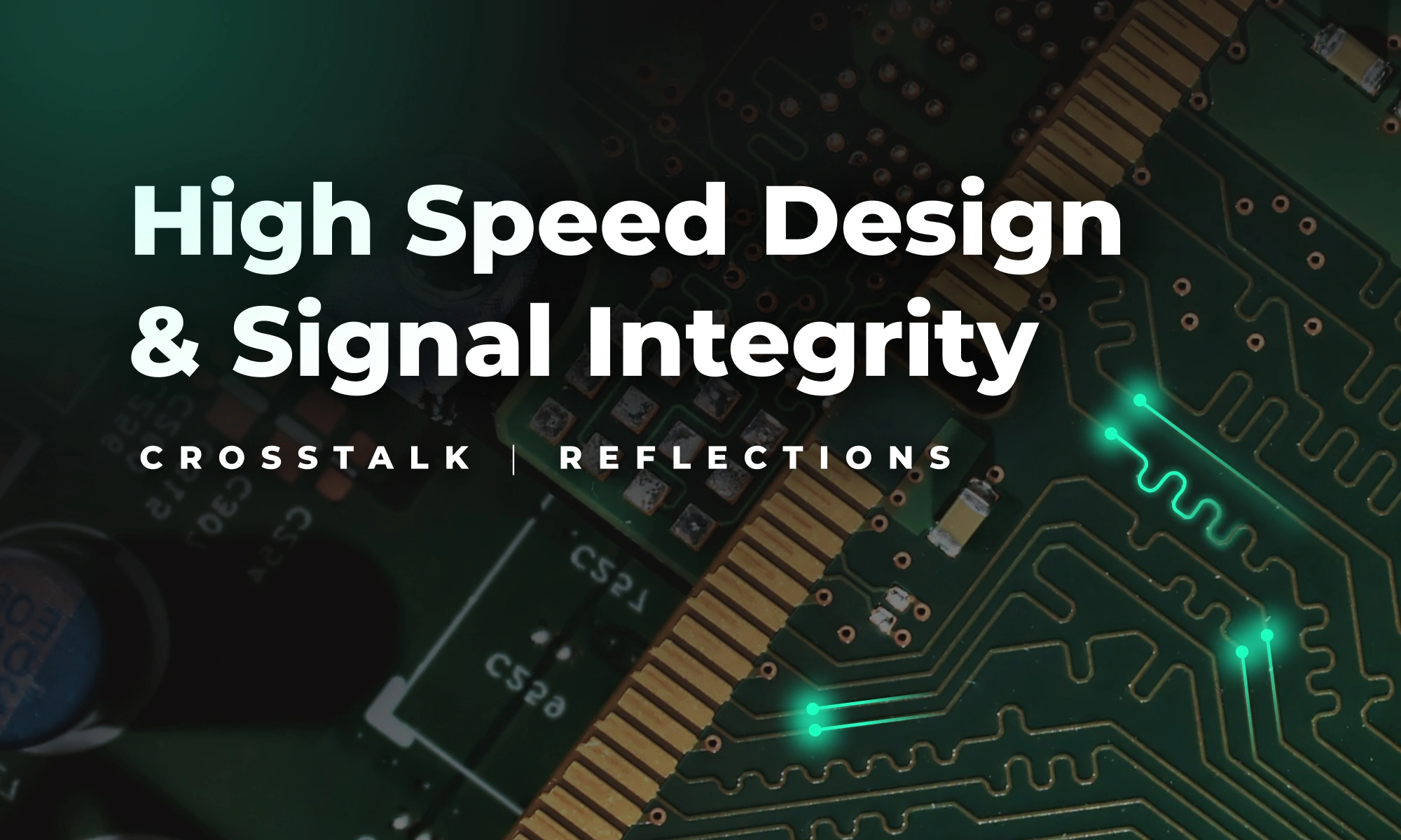
This is what Signal and Power Integrity (SI/PI) is all about, and why it’s critical even for everyday designs.

What’s Actually Going Wrong?

Signal integrity issues fall into three buckets:

  1. Reflections – When impedance is mismatched at connectors, vias, or stubs, energy reflects back toward the source. This causes overshoot, ringing, or timing errors.
  2. Insertion loss – High-frequency signals degrade as they move through lossy materials or poorly routed traces. Eye diagrams close up, jitter increases, and edge rates slow down.
  3. Crosstalk – Aggressor nets couple into nearby “victim” nets, injecting noise via mutual capacitance and inductance. This reduces your signal-to-noise ratio and corrupts data.

If you’re using fast clocks, long runs, or high-speed I/O—even on a two-layer board—these issues can bite.

What Is Crosstalk (And How to Spot It)?

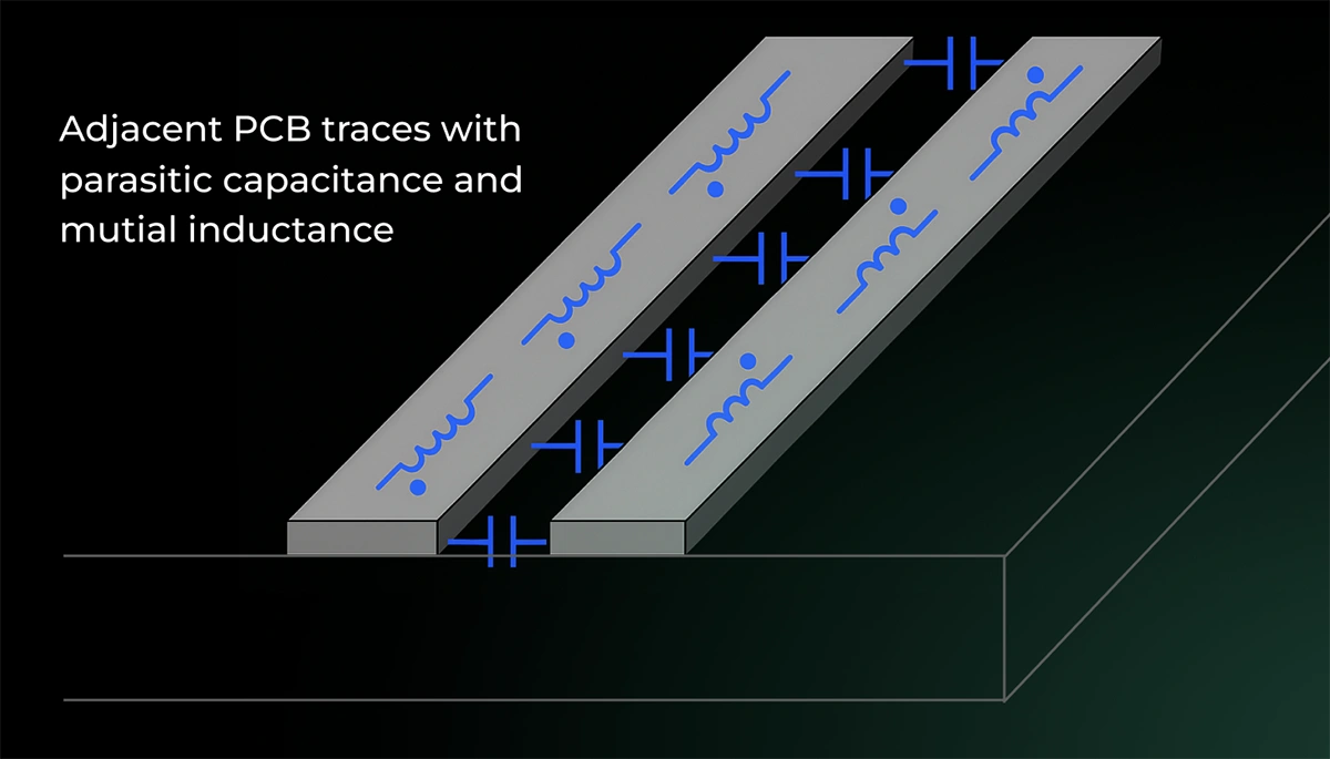
Crosstalk happens when traces run too close in parallel. The energy from one net bleeds into the other, distorting waveforms and injecting unpredictable noise.

You’ll see false triggers or glitches in digital nets, unexpected ripple in analog sections and most of the times -- EMI issues in test.

Want a shortcut? If your trace spacing is less than 3× the width, and they run in parallel for more than a few centimeters, you probably have crosstalk.

5 Ways to Reduce Crosstalk Today

You don’t need a PhD or 8-layer board to fix this. Try these:

  • Increase spacing — Keep parallel nets ≥3× trace width
  • Use guard traces — Add grounded traces between high-speed lines
  • Stick to stripline — Route sensitive nets between ground planes
  • Control return paths — Avoid routing across plane splits
  • Maintain symmetry — For differential pairs, match spacing and lengths

It’s Not Just About Routing

Board materials, stack-up, impedance, and even your decoupling caps play a role.

If your stack-up lacks solid return planes, or your dielectric isn’t up to spec, no amount of “good routing” will save you.

You Don’t Have to Be an Expert, But You Do Need a Plan

This is why we put together a complete guide that breaks down:

  • How to characterize your signals
  • What to ask from your PCB house
  • How to choose materials and trace geometries
  • Where to place stitching vias and capacitors
  • How to validate performance before the lab

📘 Download the full Signal Integrity PDF Guide

With checklists, diagrams, and cheat sheets to design boards that work the first time, for FREE.

{{download-high-speed-guide}}

|
June 20, 2025